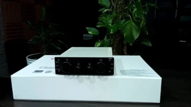
Designing a High-End DAC with 4 ESS ES9039PRO Chips

Minimally distorting the waveforms of audio signals is achieved through the processing of Digital-to-Analog Converters (DACs), which are components in high-fidelity audio systems. One of the most advanced DAC chips, the ESS Technology ES9039PRO, uses 4 watts of power while delivering astonishing performance with THD+N polyphony of -140 dB. It also supports 32 PCM and DSD1024 playback.
Paralyzing 4 ESS9039PRO chips improves performance further by reducing noise, improving channel separation, and increasing dynamic range. This article describes the advantages and drawbacks of constructing a high-end DAC using 4 ESS ES9039PRO chips alongside the design considerations of the circuit.
Why Use 4 ES9039PRO Chips?
1. Improved Signal-to-Noise Ratio (SNR)
- Every ES9039PRO chip comes with an SNR specification of 140 dB.
- When four chips are connected in parallel, noise gets averaged out, providing SNR improvement.
2. Lower Distortion
- Parallel DACs reduce harmonic distortion by sharing the workload.
- The multi-DAC approach enhances the ESS HyperStream IV modulation.
3. Enhanced Current Output
- An output current architecture is featured by the ES9039PRO.
- The performance of the analog stages is improved by merging four DACs, which increases the current drive capacity.
4. Better Channel Separation
- Per-channel dedicated DACs, for example, two chips for one stereo channel, effectively eliminate crosstalk.
Design Considerations for a Quad ES9039PRO DAC
1. Digital Input & Signal Distribution
- USB (XMOS or Amanero), I2S, S/PDIF, AES/EBU are all supported.
- Clock Alignment: A master clock, CCHD-957, introduces low jitter and thus ensures minimal phase noise.
- FPGA or DSP needs to be used: For one to divide the digital signal for four DACs.
2. DAC Configuration
- Mono vs. Stereo Mode:
- Mono Mode: One DAC per channel (left or right) assigned to each.
- Stereo Mode: Two DACs assigned per channel.
- I/V Conversion:
- With each ES9039PRO declared as an I current source, excellent I/V converters such as discrete op-amps or transformers are needed.
- Example: Duse I/V stages with Discrete JFETs or Lundahl LL1545A transformers.
3. Power Supply Design
- Ultra-Low Noise Linear Regulators: Properly designed can dramatically reduce power supply noise.
- Example: LT3045 ultra-low-noise LDOs for analog sections.
- Separate Power Rails: The digital, analog, and clock sections should each have their dedicated power supply.
4. Analog Output Stage
- Balanced vs. Single-Ended:
- Balanced (Differential): Better noise rejection; requires differential amplifiers.
- Single-Ended: Simpler but may introduce more noise.
- Output Buffer: A high-performance op-amp (e.g., Sparkos Labs SS2590) or discrete Class-A amplifier.
5. PCB Layout & Shielding
- Separation of the Ground Plane: Digital and analog grounds must be separated with strict control.
- Shielding: RF shielding for vulnerable analog line works.
- Short Signal Paths: Reduction of interference as well as improvement in signal degradation.
Performance Benefits
| Specification | Single ES9039PRO | Quad ES9039PRO (Parallel) |
|---|---|---|
| THD+N | -140dB | Improved (lower) |
| SNR | 140dB | 145dB+ (estimated) |
| Dynamic Range | 140dB | 145dB+ |
| Output Current | Moderate | 4x Higher |
| Channel Separation | Excellent | Near-Perfect |
Challenges & Solutions
1. Increased Complexity
- Solution: Use an FPGA (e.g., Xilinx) to manage signal distribution.
2. Heat Dissipation
- Solution: Proper heatsinking and thermal management.
3. Cost
Solution: Optimize design for high-end audiophiles or professional markets.
- Solution: Optimize design for high-end audiophiles
Example Implementation: A Reference Design
- Digital Input: XMOS XU316 USB interface.
- Clock: Crystek CCHD-957 (femto-second jitter).
- DAC Array: 4 ES9039PRO in mono mode (2 per channel).
- I/V Stage: Discrete JFET-based design.
- Output: Fully balanced with Lundahl transformers.
- Power Supply: Multiple LT3045 regulators with separate transformers.
Conclusion
SNR, dynamic range, distortion, and other factors make a device that steers audio signals through 4 ESS ES9039PRO chips perform at its peak and is unparalleled in the industry. Though the effort required to construct it is tremendous and expensive, the resulting quality of the audio created from audiophile systems, mastering studios, and ultra-high resolution playback systems perfectly justifies the exceptional cost.
Exceeding a single-chip solution’s capabilities can be reached by meticulously controlling power supply noise, signal distribution and stages of output voltages.
Would a schematic or a part list tailored to a design like this appeal to you? Tell me what I could alter to make this more appealing!


